How to build a Y3MD
The Y3MD is Ypsilanti Ann Arbor Area
Robotics Club's design for a 3 channel Motor Driver. It acts as an
H-bridge amplifier, so a small processor like a Basic Stamp or a LEGO Mindstorms
RCX can drive much larger motors, such as those found in Barbie Ride-On Jeeps.
Each channel of the motor driver can easily drive a 30 amp, 12 volt motor.
There are 3 channels, to match the 3 motor outputs on a LEGO Mindstorms RCX.
The outputs can be run in parallel to drive higher current motors.
The boards can be cut into 3 sections for individual H bridges.
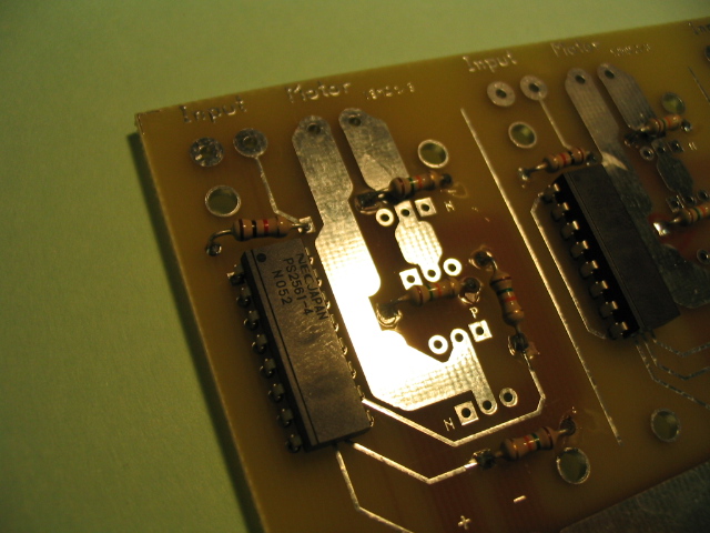
It is a simple circuit. With no input, the N channel MOSfets are kept
turned off by the 15k pull up resistors, likewise for the P channel
MOSfets, except their resistors are wired to pull down. Each LED in
the optoisolator is coupled to a phototransistor. Each phototransistor
drives a MOSfet. The LEDs are wired so that 1 pair will be turned on by a
positive voltage, the other pair will be turned on by a negative voltage.
It is impossible to turn on both pairs of LEDs at the same time. Which means
that it is impossible to turn on both pairs of MOSfets at the same time.
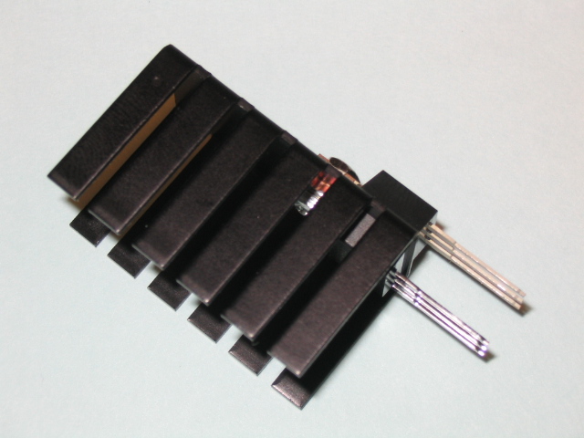
Each P channel MOSfet shares a heatsink with an N channel MOSfet. If
the circuit is built correctly, it is
impossible for both MOSfets on a heatsink to be on at the same time.
I had a bad solder joint on a pullup resistor on the first prototype, which
was on a circuit board with wimpy little traces.
Without that pullup resistor, it was possible for both MOSfets to be on
at the same time. The MOSfets failed and the wimpy traces blew up.
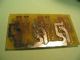
These circuit boards have very wide traces, so the MOSfets explode without
damaging the circuit board.
- Identify the parts
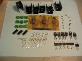
- 6 TO-220 PWR CLR 1.45"10W heat sinks
- 9 Connectors 3 power, 3 motor, 3 input.
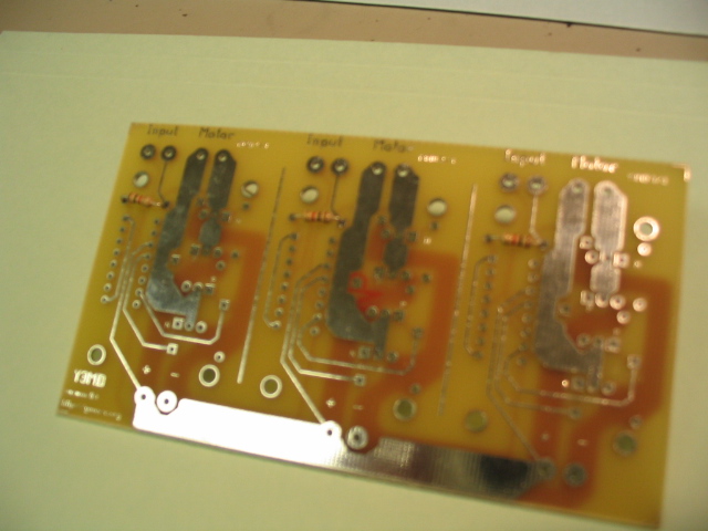
- 1 Y3MD circuit board
- 6 4-40 nuts
- 6 4-40 .25 inch screws
- 3 PS2501-4 4 channel Opto isolators
- 3 1k resistors LED current resistor.
- 12 15k resistors pullup resistors.
- 6 IRF4905,
55V, 74Amp P channel MOSfet install next to the P on the circuit board.
- 6 IRF1010N 55V, 85Amp N channel MOSfet install next to the N on the circuit board.
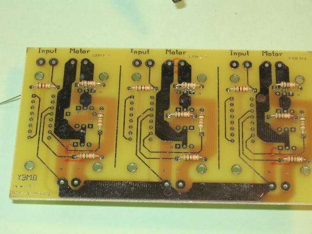
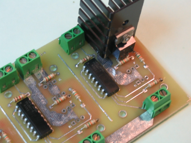
- mount resistors,
component side is the side with words.
- Install the 3, 1K Ohm resistors (current limit for LEDs for optoiso).
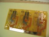
- Install the 12, 15K Ohm resistors (pull up or down resistors for MOSfets).
CAUTION. If you have a bad joint on any one of these resistors,
the smoke will come out of a P channel MOSfet!
check those solder joints
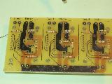
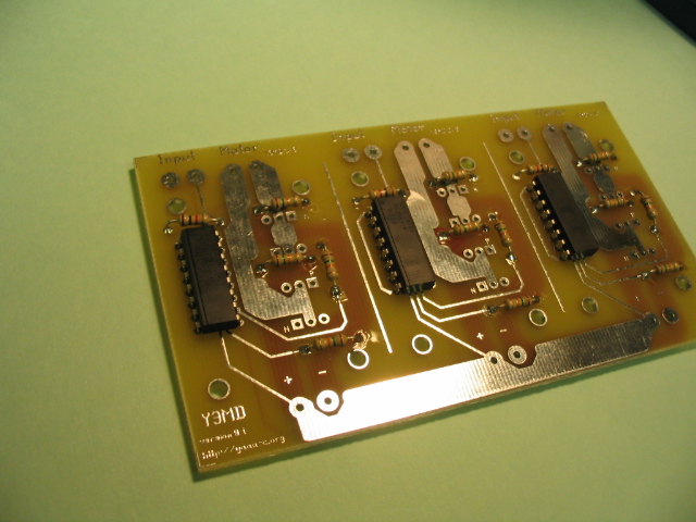
- mount the optoisolators
Pin 1 is the square pad. Upper left corner.
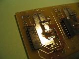
Insert each chip
Bend pins on opposite corners of the chips, to hold the chip on when you
flip the board over to solder.
Solder them.
- mount connectors. Make sure the openings point out.
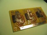
- identify and install the MOSfets.
Note that pairs of MOSfets share a
- IRF4905, P channels go next to the P.
- IRF1010N, N channels go next to the N.
Screw goes into the hole in the N channel MOSfet.
Put the N channel and screw onto the heatsink so the threads stick out the bottom of the "U".
P channel onto the threads.
Then the nut.
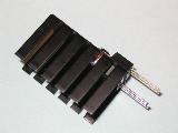
Repeat for all 6 pairs of MOSfets.
- Solder in the MOSfets.

- Test it with a 1KOhm resistor in series with the power supply. This will provide enough
current to light an LED, but not enough to blow up a MOSfet.
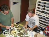
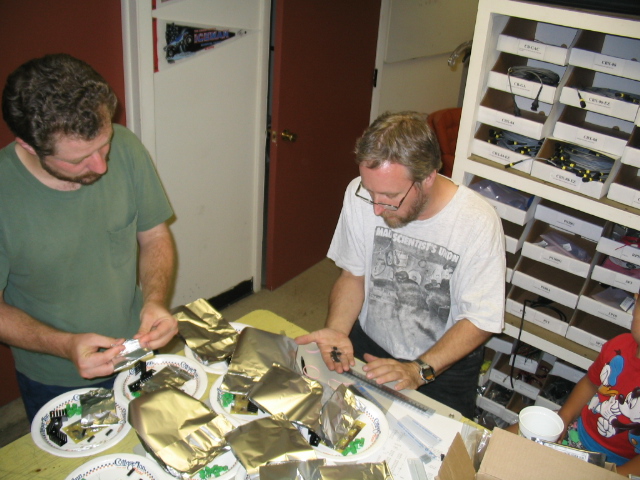
Here are George and Erik sorting the parts to make the first 10 kits.